


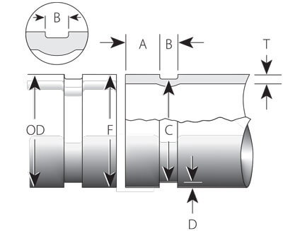
| Nominal size | Pipe OD | Min wall Thickness (T) | Gasket seat (A) -0.76/+0.38 | Groove width (B) -0.38/+0.76 | Groove diameter (C) | Groove depth (D) | Max flaring diameter (F) | ||||
|---|---|---|---|---|---|---|---|---|---|---|---|
| OD | Tolerance (mm) | Average | Tolerance +0.00 | ||||||||
| Inch | DN | mm | - | + | mm | mm | mm | mm | mm | mm | mm |
| 1" | 25 | 33.4 | 0.33 | 0.33 | 1.65 | 15.88 | 7.14 | 30.23 | -0.38 | / | / |
| 1-1/4" | 32 | 42.2 | 0.41 | 0.41 | 1.65 | 15.88 | 7.14 | 38.99 | -0.38 | / | / |
| 1-1/2" | 40 | 48.3 | 0.48 | 0.48 | 1.65 | 15.88 | 7.14 | 45.09 | -0.38 | / | / |
| 2" | 50 | 60.3 | 0.61 | 0.61 | 1.65 | 15.88 | 8.74 | 57.15 | -0.38 | / | / |
| 2-1/2" | 65 | 73.0 | 0.74 | 0.74 | 2.11 | 15.88 | 8.74 | 69.09 | -0.38 | / | / |
| 3" | 80 | 88.9 | 0.79 | 0.89 | 2.11 | 15.88 | 8.74 | 84.94 | -0.38 | / | / |
| 4" | 100 | 114.3 | 0.79 | 1.14 | 2.11 | 15.88 | 8.74 | 110.08 | -0.38 | / | / |
| 5" | 125 | 141.3 | 0.79 | 1.42 | 2.77 | 15.88 | 8.74 | 137.03 | -0.38 | / | / |
| 6" | 150 | 168.3 | 0.79 | 1.60 | 2.77 | 15.88 | 8.74 | 163.96 | -0.38 | / | / |
| 8" | 200 | 219.1 | 0.79 | 1.60 | 2.77 | 19.05 | 11.91 | 214.40 | -0.51 | / | / |
| 10" | 250 | 273.1 | 0.79 | 1.60 | 3.40 | 19.05 | 11.91 | 268.27 | -0.64 | / | / |
| 12" | 300 | 323.9 | 0.79 | 1.60 | 3.96 | 19.05 | 11.91 | 318.29 | -0.64 | / | / |
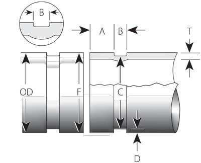
| Nominal size | Pipe OD | Min wall Thickness (T) |
Gasket seat (A) ±0.76 | Groove width (B) ±0.76 | Groove diameter (C) | Groove depth (D) | Max flaring diameter (F) |
||||
|---|---|---|---|---|---|---|---|---|---|---|---|
| OD | Tolerance (mm) | Actual | Tolerance +0.00 | ||||||||
| Inch | DN | mm | - | + | mm | mm | mm | mm | mm | mm | mm |
| 1" | 25 | 33.7 | 0.33 | 0.33 | 1.65 | 15.88 | 7.14 | 30.23 | -0.38 | 1.73 | 36.3 |
| 1-1/4" | 32 | 42.4 | 0.41 | 0.41 | 1.65 | 15.88 | 7.14 | 38.99 | -0.38 | 1.70 | 45.0 |
| 1-1/2" | 40 | 48.3 | 0.48 | 0.48 | 1.65 | 15.88 | 7.14 | 45.09 | -0.38 | 1.60 | 51.1 |
| 2" | 50 | 60.3 | 0.61 | 0.61 | 1.65 | 15.88 | 8.74 | 57.15 | -0.38 | 1.57 | 63.0 |
| 2-1/2" | 65 | 73.0 | 0.74 | 0.74 | 2.11 | 15.881 | 8.742 | 69.09 | -0.46 | 1.95 | 75.7 |
| 2-1/2" | 65 | 76.1 | 0.76 | 0.76 | 2.11 | 15.88 | 8.74 | 72.26 | -0.46 | 1.92 | 78.7 |
| 3" | 80 | 88.9 | 0.79 | 0.89 | 2.11 | 15.88 | 8.74 | 84.94 | -0.46 | 1.98 | 91.4 |
| 4" | 100 | 114.3 | 0.79 | 1.14 | 2.11 | 15.88 | 8.74 | 110.08 | -0.51 | 2.11 | 116.8 |
| 5" | 125 | 139.7 | 0.79 | 1.42 | 2.77 | 15.88 | 8.74 | 135.48 | -0.51 | 2.11 | 142.2 |
| 5" | 125 | 141.3 | 0.79 | 1.42 | 2.77 | 15.881 | 8.742 | 137.03 | -0.38 | 2.13 | 143.8 |
| 6" | 150 | 165.1 | 0.79 | 1.60 | 2.77 | 15.88 | 8.74 | 160.78 | -0.56 | 2.16 | 167.6 |
| 6" | 150 | 168.3 | 0.79 | 1.60 | 2.77 | 15.881 | 8.742 | 163.96 | -0.56 | 2.17 | 170.9 |
| 8" | 200 | 219.1 | 0.79 | 1.60 | 2.77 | 19.05 | 11.91 | 214.4 | -0.64 | 2.35 | 223.5 |
| 10" | 250 | 273.0 | 0.79 | 1.60 | 3.40 | 19.05 | 11.91 | 268.28 | -0.69 | 2.36 | 277.4 |
| 12" | 300 | 323.9 | 0.79 | 1.60 | 3.96 | 19.05 | 11.91 | 318.29 | -0.76 | 2.80 | 328.2 |